Battery Pack Thermal Management for Motive Power Equipment
Thermal design for industrial LiFePO4 battery packs is not only about adding cooling. For floor cleaning machines, aerial work platforms, utility vehicles, AGVs and other motive power equipment, OEMs need to control heat sources, current paths, enclosure layout, BMS temperature sensing and validation from the first design review.
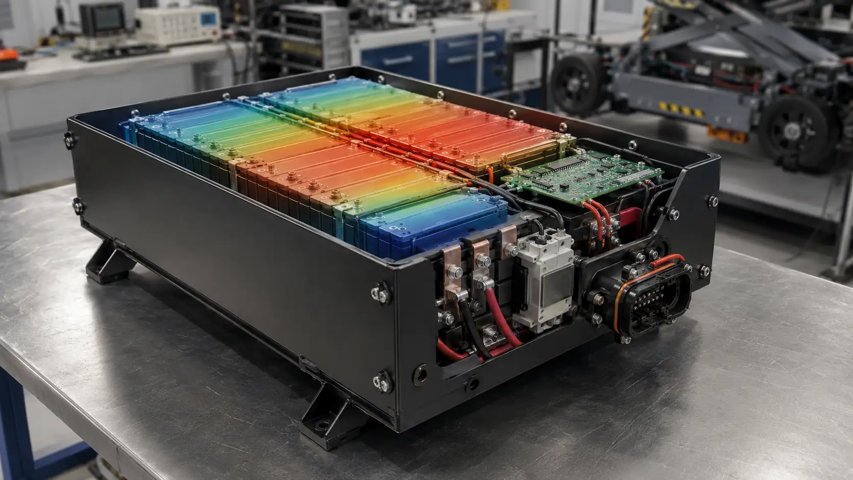
Heat is a system result, not a single component problem
In motive power applications, a LiFePO4 battery pack may work under repeated acceleration, motor startup current, long discharge periods, opportunity charging, vibration, limited battery compartment space and different ambient temperatures. Even when the cell chemistry is stable, poor thermal design can still create hot spots around cables, connectors, contactors, busbars or tightly packed cells.
That is why thermal management should be considered together with voltage platform, pack size, duty cycle, enclosure, BMS settings, charger matching and the vehicle-side wiring interface. A pack used in a walk-behind scrubber is not exposed to the same heat pattern as a 72V aerial work platform or a 96V utility vehicle.
For OEM projects, Chalongfly normally reviews thermal risk together with motive power battery application requirements, mechanical packaging, connector layout, BMS protection logic and validation plans before sample production.
OEM takeaway
A good thermal design does not simply keep the pack “cool.” It keeps temperature distribution predictable under the customer’s real duty cycle, so the BMS can protect the battery without unnecessary shutdowns, derating or connector overheating.
Best timing: thermal review should happen before the steel case, cable exit, connector position and BMS sensor locations are frozen.
Thermal risk map inside a motive power battery pack
Thermal management starts by identifying where heat is generated, where it can accumulate and how it can leave the pack safely.
Cell zone
Cells produce heat during high-current charge and discharge. Temperature differences between cell groups can affect BMS balancing, usable capacity and protection behavior.
- Cell spacing and compression structure
- Temperature sensor coverage
- Pack orientation and heat path to enclosure
- Continuous vs peak current duty cycle
Power path zone
Cables, busbars, fuses, contactors, service disconnects and pre-charge components may become local hot spots when current rating, contact resistance or layout is not matched.
- Cable cross-section and routing length
- Busbar contact surface and torque control
- Fuse and contactor temperature rise
- Separation between power and signal wiring
Interface zone
High-current connectors and battery-side terminals must be reviewed as part of the thermal system, especially for equipment with frequent charging, vibration or service access.
- Connector current rating and derating
- Contact resistance after vibration
- Strain relief and cable bend radius
- Heat around sealed cable exits
Thermal design should be built into the pack architecture
For industrial batteries, heat problems often appear late because the project first focuses on voltage, capacity and case size. In practice, thermal behavior is linked to almost every design decision: cell configuration, BMS protection, enclosure material, cable sizing, connector location and charger current.
Send Duty Cycle for ReviewDefine the real operating profile
Start with equipment current demand, motor startup peak, continuous discharge time, charging frequency, ambient temperature and whether the battery is inside a closed compartment.
Choose cell configuration and current margin
Thermal stress changes with cell capacity, series-parallel configuration and pack current. A 48V industrial pack may need different design margins from 72V or 96V motive power systems. See the 48V LiFePO4 battery pack design guide for related voltage platform considerations.
Review enclosure and mounting conditions
A steel case battery pack can support structural protection and heat spreading, but only when internal contact surfaces, clearance, insulation and equipment-side mounting are considered together.
Place BMS temperature sensors where they matter
A single sensor at a convenient position may not represent the hottest cell group or the power path. BMS logic should reflect cell zone, power component zone and ambient condition near the pack.
Validate with application-level testing
Thermal performance must be checked under realistic charging and discharging conditions. For rental or fleet equipment, the validation method should consider repeated usage, operator behavior and service cycles.
Key design areas OEMs should review
Thermal management is a combined review of electrical, mechanical and control logic. The table below shows the areas that usually need attention before sample approval.
| Design area | Thermal risk | What to review | OEM decision point |
|---|---|---|---|
| Cell layout | Uneven temperature distribution between cell groups | Cell spacing, compression structure, insulation sheet, sensor coverage and heat path to the enclosure | Before case tooling |
| BMS temperature sensing | Late protection, unnecessary shutdown or missed hot spot | Sensor number, placement, warning threshold, derating logic and fault recovery strategy | Before sample build |
| Cable and busbar path | Local heat from undersized conductors or poor contact surface | Cable size, route length, bend radius, busbar surface, torque process and insulation clearance | Before wiring layout freeze |
| Connector interface | Heat rise from contact resistance, vibration or overloaded connector pins | Connector current rating, derating, mating cycles, strain relief and service access. Chalongfly can support TE connector selection and supply for OEM projects through its TE Tier-1 distributor resources in China. | Before vehicle-side harness freeze |
| Charger matching | Excessive heat during repeated charging or high ambient conditions | Charge current, charge voltage, BMS communication, temperature derating and charger stop logic | Before sample testing |
| Battery compartment | Heat accumulation in closed or poorly ventilated equipment space | Available air volume, clearance, nearby heat sources, mounting rails, cable exit position and service space | Before equipment integration |
Temperature margin
Define acceptable pack temperature behavior under real work cycles instead of relying only on cell datasheet values.
BMS response
Set warning, derating and protection logic according to the equipment’s operating pattern, not only laboratory current values.
Connector heat
Review connector and cable temperature rise together, especially where vibration and repeated charging are expected.
Validation data
Record temperature at cells, power path and interface points during charge, discharge and peak-current events.
How to validate thermal behavior before mass production
Thermal validation should simulate the customer’s real operating conditions as closely as possible. For motive power equipment, this usually requires more than a simple capacity test.
1. Baseline check
Measure initial internal resistance, connector resistance, harness condition and pack temperature before load testing.
2. Discharge cycle
Run continuous and peak-current profiles that match equipment operation, including motor startup or lifting events.
3. Charge cycle
Test charger profile, BMS response and temperature rise during normal and opportunity charging conditions.
4. Compartment test
Install the battery in the actual equipment space to check heat accumulation, cable clearance and service access.
5. Review report
Use test data to adjust BMS thresholds, sensor positions, cable size, connector selection or case design before mass production.
For fleet applications, thermal validation should be combined with serviceability and rental-cycle testing. See our guide on validating LiFePO4 battery packs for MEWP rental fleets for a related validation approach.
Different motive power equipment creates different heat patterns
A thermal solution that works for one equipment platform may not be suitable for another. OEMs should review battery thermal behavior by application, not only by voltage and capacity.
Motor startup and compact compartments
Walk-behind and ride-on cleaning machines often have limited battery space, repeated motor startup and exposure to cleaning environments. Thermal design should consider compartment clearance, charger matching and connector sealing.
Peak current and rental duty cycles
Scissor lifts and boom lifts may experience high current during lifting, driving and steering. Rental fleets also require stable protection behavior after repeated charge-discharge cycles.
Long discharge and outdoor ambient
Low-speed electric vehicles and industrial utility vehicles may operate for long periods, often with high-current acceleration and different ambient conditions. Pack thermal margin and connector derating become important.
Frequent charging and communication
AGV and AMR systems may use charging docks, automated charging logic and communication with the vehicle controller. Thermal review should include both charging and BMS communication behavior.
Quiet operation and safe enclosure design
Medical mobile equipment may require compact, low-noise and service-friendly battery packs. Thermal management should avoid unnecessary active cooling unless the duty cycle requires it.
Sealed spaces and load diversity
Marine and RV battery packs may be installed in semi-enclosed spaces and support inverter loads. Thermal behavior should be reviewed together with enclosure sealing, cable length and charging source.
What OEMs should provide for a thermal design review
To evaluate thermal risk accurately, the battery supplier needs more than voltage and capacity. The most useful information is the real equipment duty cycle and installation environment.
FAQ about motive power battery thermal management
Do LiFePO4 motive power battery packs always need active cooling?
No. Many motive power LiFePO4 battery packs can use passive thermal design when the cell configuration, current margin, enclosure, cable size and installation space are properly matched. Active cooling should be considered only when the duty cycle, ambient temperature, enclosure sealing or power demand requires it.
What causes heat inside an industrial lithium battery pack?
Heat can come from cells under high current, busbars, cables, fuses, contactors, service disconnects, connectors, charger current and poor contact resistance. In many OEM projects, the hottest area is not always the cell zone; it may be the power path or the connector interface.
Where should BMS temperature sensors be placed?
Temperature sensors should be placed where they can represent the real thermal risk, including cell groups, likely hot spots and power component areas when needed. A single convenient sensor position may not detect the highest pack temperature during peak current or charging.
Does a steel case improve battery pack thermal management?
A steel case can provide mechanical strength and may help spread heat when the internal layout supports a proper heat path. However, a steel enclosure can also retain heat if the pack has poor clearance, blocked cable exits or limited heat transfer to the equipment structure.
What information should OEMs provide for thermal design?
OEMs should provide the equipment type, continuous and peak current, discharge profile, charger current, battery compartment drawing, mounting direction, ambient temperature range, sealing requirements, connector position and service-access requirements. This helps the battery supplier design and validate the pack under realistic conditions.
Need a thermal review for a motive power battery project?
Send your battery compartment drawing, current profile, charger information and connector requirements. Chalongfly can review pack layout, BMS temperature sensing, enclosure design, cable and connector heat risk before sample production.