


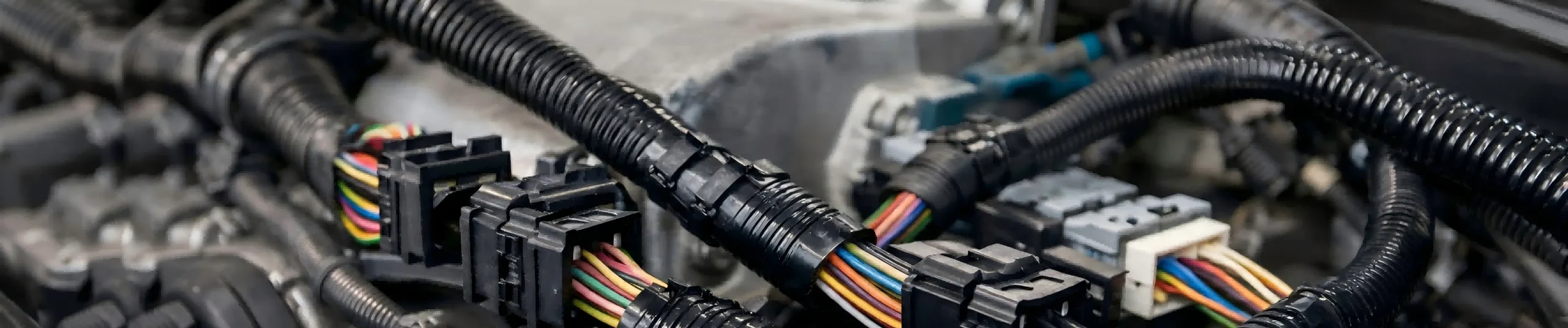
Automotive Wire Harnesses
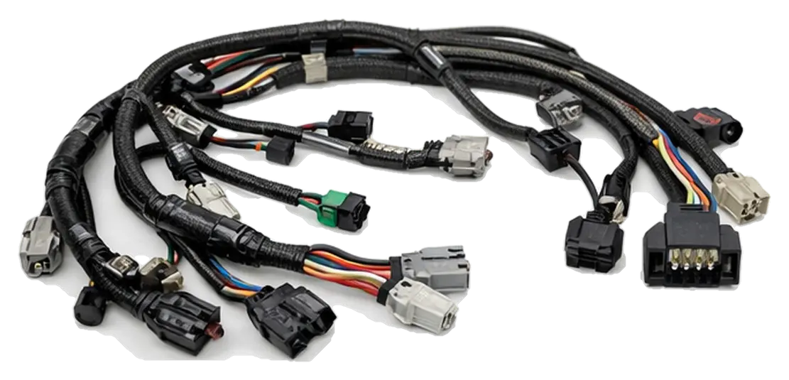
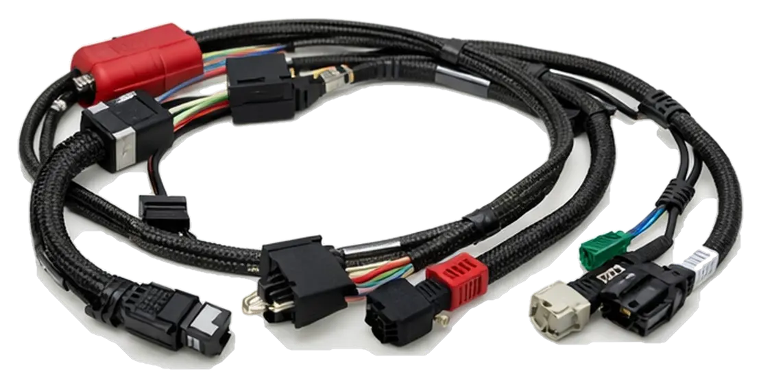
OEM Automotive Wire Harness Assembly Services
Chalong Fly coordinates OEM/ODM automotive wire harness programs for EV, HEV and conventional vehicle applications. Project scope can cover power, auxiliary and signal circuits based on customer drawings, BOMs, samples and specified operating conditions. We support OEM/ODM projects from prototype sampling to mass production based on your drawing/BOM and application requirements.
Professional Wiring Solutions
- Comprehensive Supply: Power harnesses, signal harnesses, and hybrid assemblies (project-based).
- Routing & Integration: Branches, labels, clips and bundling are defined from the installation route, connector interface and customer drawing.
- Protection Options: Sleeves, corrugated tubes, heat-shrink, seals and strain relief can be specified against temperature, vibration, moisture, abrasion and chemical exposure.
- Pin-to-Pin Mapping: Connector mapping and polarity checks are performed to the approved project requirements.
RFQ Checklist: Share the drawing/BOM or sample, circuit function, voltage/current, wire size and route, connector part numbers/pinout, quantities, environment, applicable vehicle/customer standards and requested inspection or test records. Mark open values TBD.
Design Capability & QC Flow
Project engineering review focuses on electrical fit, manufacturability and installation practicality. Crimping, branch layout, strain relief and abrasion protection are coordinated to the approved drawing, terminal specification and build scope.
- Electrical Design: Wire gauge selection, branching logic, and voltage drop considerations.
- Signal/EMI: Optional twisted pairs, shielding, and grounding strategies when required.
- Manufacturing & QC Scope: Crimping and assembly checkpoints can be defined with incoming-material, continuity, short-circuit and polarity checks in the approved project plan; pull-force or insulation-resistance tests are included when specified, applicable and agreed.
Typical Applications
- Automotive: Passenger & commercial vehicles, body wiring, lighting, and sensor harnesses.
- EV / Mobility: Auxiliary power, low-voltage control, and pumps/fans.
- Industrial: Off-road equipment, AGV/AMR, and specialized carts.
Project-defined checks: Pinout/polarity, connector engagement and continuity/short checks can be included in the agreed acceptance plan. Hi-Pot, insulation resistance or pull-force tests are scoped only when the design, applicable requirements and customer test plan call for them.
| Mechanical & Materials | |
|---|---|
| Conductor | Copper (tinned copper optional) |
| Insulation | Customer-specified PVC / XLPE / silicone, selected for the defined temperature and environment |
| Protection | Corrugated tube / Braided sleeve / Heat-shrink |
| Wire Gauge | Project-based (AWG / mm²) |
| Process & Compliance | |
|---|---|
| Terminal Process | Crimp tooling/parameters per terminal specification; soldering only when specified |
| Standard Test | Continuity and short-circuit checks per approved project test plan |
| Labeling | Part number/revision labels; optional QR fields by project agreement |
| MOQ | Project-based (prototype supported) |
From Drawing to Mass Production
1) Input & Review (DFM): Review the customer drawing/BOM and revision, clarify circuit roles and interfaces, and list open material, routing or test-scope questions before sample planning.
2) Prototype & Approval: Where sampling is in scope, agree the sample configuration and fit/interface checks, then capture customer feedback and approval before production release.
3) Production & Delivery: Coordinate sourcing, assembly checkpoints, inspection and end-of-line checks to the approved order and quality plan; required records and acceptance evidence are confirmed for the program.
Project handoff: A reviewed build definition, agreed inspection/test scope and supply coordination for the approved program.
Automotive Harness Engineering Considerations
Vehicle harness requirements vary by circuit, architecture and installation environment. We review the customer drawing, BOM, sample and applicable vehicle or customer requirements before confirming a build scope.
High-Voltage Traction & Charging
For EV/HEV traction, battery or charging interconnects, define the design voltage, continuous/peak current, route, connector interface, insulation, protection and relevant vehicle safety requirements. Cable, terminal and sealing choices are confirmed against the approved design; no voltage or current capability is assumed from this general page.
Low-Voltage Power Circuits
Auxiliary loads such as pumps, fans, lighting and body functions are reviewed by load profile, conductor cross-section, run length, allowable voltage drop, fuse/interface requirements and the temperature around the route. Provide inrush or peak-load details when they affect selection.
Signal, Sensor & Control
Sensor, communication and control circuits depend on the pinout, signal type, grounding and separation from power paths. Twisted pairs, shielding or drain-wire arrangements can be specified when required by the system design and verified against the customer's interface requirements.
Materials, Routing and Environmental Inputs
Conductors:
Copper type, cross-section, strand construction, color and length based on current, route and voltage-drop requirements.
Terminals and connectors:
Part number, mating interface, plating/seal option, pin assignment and sourcing confirmation from the approved BOM.
Insulation and protection:
Material, sleeve, corrugated tube, seal, clip, shielding and strain relief selected for the specified temperature and exposure.
Vehicle environment:
Identify vibration, humidity/water, abrasion, fluid/chemical exposure and routing constraints; target conditions and acceptance limits must come from the project requirements.
Compliance:
Where RoHS or another substance/customer requirement applies, identify the exact scope and requested supplier declarations or records for the components in the BOM.
Sample Approval and Quality Plan
Before a production release, align the drawing/BOM revision, connector mapping, sample feedback and acceptance criteria. Depending on the design and agreed plan, inspection may cover visual workmanship, pinout/polarity, connector engagement, continuity/short checks, crimp review and specified pull-force or insulation tests. Method, sampling, limits and records are confirmed for each project; this page does not promise a fixed test result or certification.
Automotive Harness RFQ Inputs
Drawing & circuit definition
- 2D/3D drawing, BOM, sample/photos and current revision
- Circuit role: HV traction/charging, LV power, sensor or communication
Electrical & interface
- Voltage, continuous/peak current, conductor size and cable route/length
- Connector/terminal part numbers, pinout, mating parts and seal needs
Environment & installation
- Temperature, vibration, moisture, abrasion, fluid/chemical exposure and vehicle installation notes
Program & acceptance
- Prototype quantity, production volume/forecast and target program milestones
- Applicable customer/vehicle standards, acceptance criteria and requested inspection/test records