Battery Wiring Harness Design Checklist for OEM LiFePO4 Battery Packs
A LiFePO4 battery pack does not depend only on cells and BMS hardware. For OEM equipment, the battery wiring harness decides how power, signals, temperature sensing, communication, charging and service access are connected safely and consistently inside the pack and at the equipment interface.
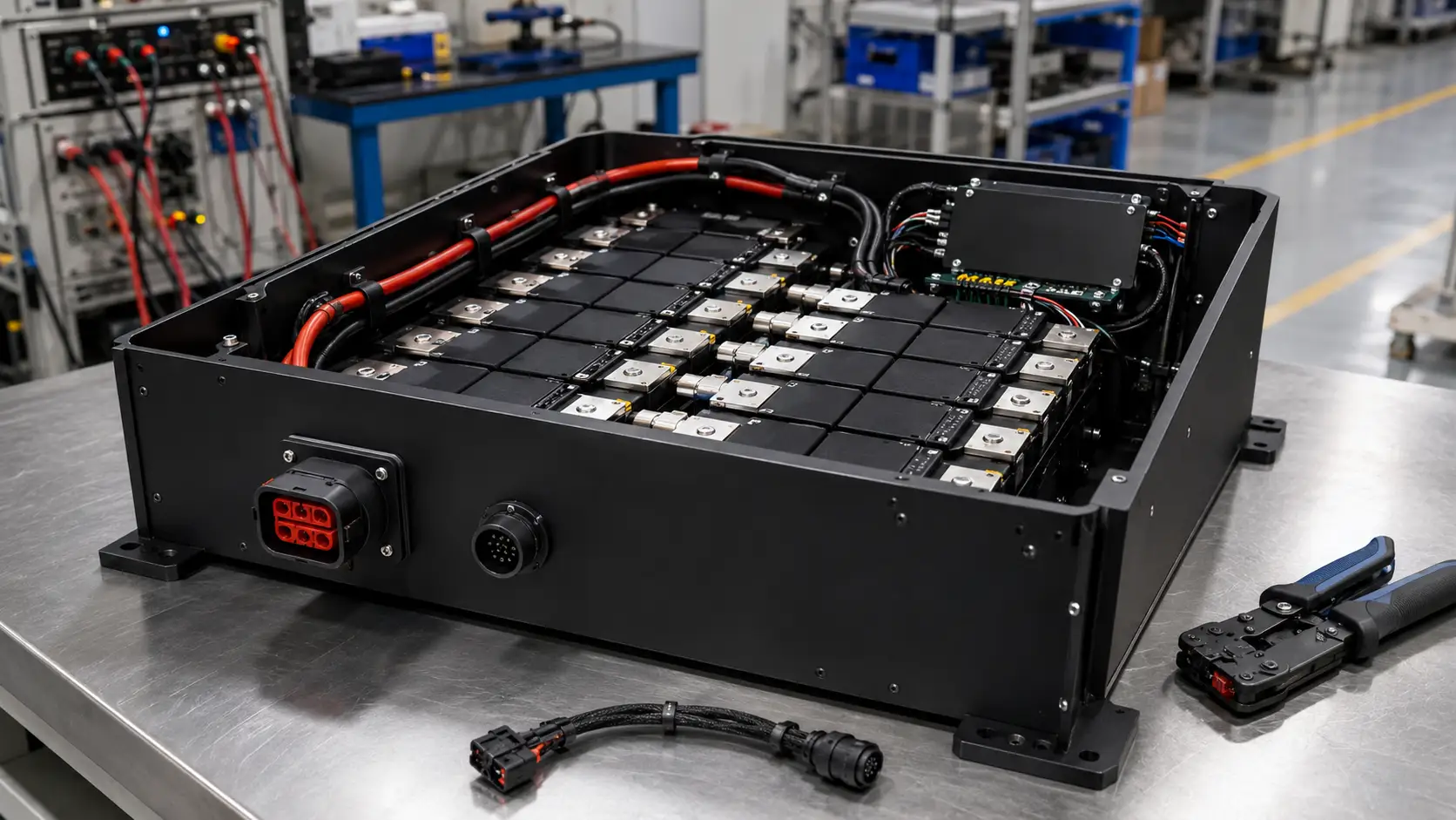
A battery wiring harness is part of the battery system, not an accessory
For OEM LiFePO4 battery packs, the wiring harness should be designed together with the cell layout, BMS, enclosure, charger, connector interface and equipment battery compartment. A proper checklist should cover power cable size, signal wire routing, connector derating, strain relief, cable exit sealing, serviceability, continuity testing, insulation checks and production inspection.
Chalongfly designs battery wiring harnesses together with custom LiFePO4 battery packs so OEMs can avoid late-stage integration problems caused by cable length, connector mismatch, signal interference or service access limitations.
Separate the battery harness into functional branches
A clean harness architecture makes the pack easier to assemble, test, diagnose and service. For motive power applications, this structure is usually more reliable than treating all wires as one bundle.
Design around current, signal, movement and service
In motive power battery projects, the harness must survive current load, vibration, repeated charging, equipment-side movement and maintenance handling. The design should define where cables run, where they are fixed, where connectors are accessed and how the BMS receives reliable data.
For 24V, 48V, 72V and 96V systems, the same basic rule applies: power and signal paths should be planned before the enclosure and connector panel are finalized.
Power cable branch
Connects cells, busbars, fuse, contactor, service disconnect, charger path and output connector. It must be sized for continuous and peak current, not only nominal voltage.
BMS signal branch
Includes balance wires, temperature sensors, voltage sense lines, enable signals and fault signals. Routing should reduce abrasion, noise and misconnection risk.
Communication branch
CAN, RS485 or other communication wiring should match the BMS and equipment controller. See our CANBus vs RS485 guide for communication selection.
Mechanical protection branch
Defines cable clamps, grommets, sleeves, bend radius, harness exits, connector locking and service loops to reduce fatigue and installation damage.
Battery wiring harness design checklist before sample build
This checklist is intended for OEM battery pack projects where the harness must be integrated with the pack enclosure, BMS, connector panel and equipment compartment.
| Checklist item | Design question | Engineering risk if ignored | Review timing |
|---|---|---|---|
| Current rating | Are power cables sized for continuous current, peak current, duty cycle and temperature rise? | Connector heating, cable heating, voltage drop, BMS derating or unexpected shutdown under high load. | Before cable layout |
| Connector interface | Does the battery-side connector match equipment current, mating direction, locking, service access and vibration conditions? | Loose connection, contact resistance, difficult installation, overheating or field-service complaints. | Before enclosure freeze |
| BMS signal routing | Are balance wires, temperature sensors and signal lines separated from high-current paths where needed? | Signal noise, wrong temperature reading, damaged sense wires or unstable BMS protection behavior. | Before BMS approval |
| Communication wiring | Is CAN, RS485 or other communication wiring matched to the equipment controller, charger and BMS protocol? | Communication failure, charger mismatch, incorrect SOC display or controller fault messages. | Before sample test |
| Strain relief | Are cable exits, connector backshells, clamps and bend radius designed to reduce mechanical stress? | Broken wires, loose crimps, water ingress around cable exits, vibration fatigue and warranty issues. | Before tooling |
| Serviceability | Can technicians connect, disconnect, inspect and replace the pack without pulling on wires or opening unsafe areas? | Field damage, slow maintenance, unsafe service access and repeated harness failure. | Before equipment integration |
| Testing plan | Are continuity, polarity, insulation, crimp pull, contact resistance and visual inspection defined for production? | Wrong wiring, hidden assembly defects, inconsistent harness quality or batch-level failure. | Before mass production |
For applications such as scissor lifts, boom lifts and industrial vehicles, connector selection should be reviewed together with harness routing. Chalongfly is a TE Tier-1 distributor in China and can support TE connector selection and supply for OEM projects. See our guide on battery connector selection for scissor lifts and boom lifts.
A practical workflow for OEM battery harness development
The harness should not be finalized after the battery pack is already built. It should be reviewed during pack architecture, equipment interface and validation planning.
1. Define equipment interface
Confirm battery compartment, connector position, charger path, service access and equipment-side mating connector.
2. Map electrical paths
Separate power, BMS sense, temperature, communication and auxiliary wiring before the harness drawing is created.
3. Build harness drawing
Define wire gauge, color, length, terminal, connector, protection sleeve, branch point and label requirements.
4. Test sample harness
Check continuity, polarity, connector mating, pull strength, bend radius, vibration exposure and installation space.
5. Freeze production criteria
Document assembly sequence, inspection points, test records and packaging method for repeatable mass production.
For higher-voltage industrial vehicle projects, harness design should be reviewed together with system voltage, peak current and charger selection. Related references include 48V LiFePO4 battery pack design, 96V lithium battery pack design and onboard vs offboard charger selection.
Battery harness problems usually appear during integration or service
Many harness problems are not visible in a clean bench test. They appear when the battery is installed into the equipment, charged repeatedly, driven under vibration or serviced by technicians.
Power and signal wires routed too closely
High-current paths can create noise, heat and service complexity around small BMS signal wires. The routing plan should protect signal wires from both electrical and mechanical stress.
Connector chosen after the case is finished
If connector position and cable bend radius are not planned early, the final pack may be hard to install, difficult to charge or unsafe to service.
No clear test criteria for harness production
Without defined continuity, polarity, crimp and inspection requirements, harness quality may vary between batches even when the drawing looks correct.
Cable exits without strain relief
Repeated vibration and service handling can damage wires near connector exits or grommets. Mechanical fixation is as important as electrical sizing.
Temperature sensors placed only for convenience
Sensor wiring should support meaningful thermal protection. Convenient placement may not represent the hottest cell group or connector-side heat source.
Service loops missing in compact compartments
Without controlled service loops, technicians may pull directly on connectors or wires during pack installation, increasing field failure risk.
What OEMs should send for a battery harness review
To design the battery harness correctly, the supplier needs the battery electrical requirements and the mechanical installation conditions. A simple voltage and capacity request is not enough.
FAQ about battery wiring harness design for OEM LiFePO4 packs
What should be included in an OEM LiFePO4 battery wiring harness?
An OEM battery wiring harness may include high-current power cables, BMS balance wires, voltage sense wires, temperature sensor wiring, CAN or RS485 communication lines, charger interface wiring, auxiliary signals, connector housings, terminals, sleeves, clamps, labels and strain relief parts. The exact structure depends on the battery pack design and equipment interface.
How should power cables and BMS signal wires be routed?
Power cables should be sized for current and routed with proper bend radius, insulation clearance and mechanical fixation. BMS signal wires should be protected from abrasion and unnecessary proximity to high-current paths. The routing should also allow stable temperature sensing, communication and service inspection.
Why is connector selection part of battery harness design?
The connector defines current capacity, mating direction, service access, vibration resistance, charging interface and equipment-side compatibility. If connector selection is delayed until after the enclosure is finished, the harness may become difficult to route, install or service.
Can Chalongfly support TE connector selection for battery harness projects?
Yes. Chalongfly is a TE Tier-1 distributor in China and can support TE connector selection and supply for OEM projects. Connector selection should still be reviewed based on current, environment, mating cycles, cable size, equipment space and service requirements.
What data should OEMs provide before harness design starts?
OEMs should provide battery voltage, continuous and peak current, BMS communication requirements, charger interface, connector preference, battery compartment drawing, cable exit direction, environmental conditions, service access needs and testing requirements. This helps the supplier design a harness that fits both the battery pack and the equipment.
Need a battery harness review for an OEM LiFePO4 pack?
Send your battery voltage, current profile, BMS communication needs, connector requirements and battery compartment drawing. Chalongfly can review power cables, signal wiring, connector selection, strain relief and production testing before sample build.