


Signal Harness Design for BMS Communication in Industrial Batteries
A BMS communication harness is not just a group of small wires. In industrial LiFePO4 battery packs, signal harness design affects CAN, RS485, cell balancing, temperature sensing, charger communication, controller feedback and fault diagnosis. This guide explains how OEM teams should review signal wiring before battery samples move into equipment testing.
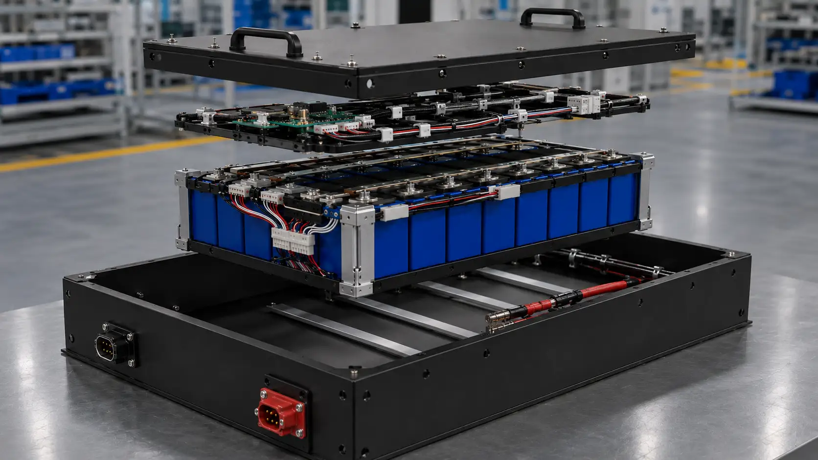
What makes BMS signal harness design different from power cable design?
Power cables are sized mainly for current, voltage drop and heat. BMS signal harnesses are designed for communication stability, sensor accuracy, connector reliability, routing separation and serviceability. A good signal harness should connect the BMS board to cells, sensors, charger, controller and external communication interface without creating noise, loose contacts or confusing service connections.
Chalongfly designs battery wiring harnesses together with custom LiFePO4 battery packs, so the BMS board, low-voltage signal harness, communication connector, high-current cable path and pack enclosure can be reviewed as one integrated system.
A practical BMS signal harness should connect five interface zones
This article does not repeat the protocol comparison in our CANBus vs RS485 BMS guide. The focus here is the physical signal harness: where the wires run, how connectors are fixed, and how the harness stays reliable inside an industrial battery pack.
The BMS receives cell voltage, temperature and current-related data, then communicates status to the charger or vehicle controller.
Pinout and connector mapping should be clear before the sample is built.
The BMS connector area should be accessible without pulling wires across the cell block.
Balance wires must follow a controlled path and avoid sharp edges, compression points or confusion during assembly.
Wire order should match the BMS channel sequence and the cell configuration.
Incorrect cell sense wiring can cause BMS faults, false readings or damage during commissioning.
Sensor locations should reflect real thermal points near cells, busbars, MOSFET zones or contactor areas as needed.
Sensor leads should be fixed to avoid movement during vibration.
Poorly fixed sensors can report the wrong battery condition during charging or discharge.
The battery may need communication with industrial chargers, traction controllers, telematics units or service tools.
Connector definition should be locked before tooling, cable length and panel layout are finalized.
Chalongfly is a TE Tier-1 distributor in China and can support TE connector selection and supply for OEM projects.
Signal wires should not be bundled tightly with high-current power cables unless shielding, routing and interference risks are reviewed.
Design depends on equipment noise, cable length and communication protocol.
Good routing helps reduce unstable communication, false alarms and difficult field troubleshooting.
What OEM engineers should define before building the first sample
BMS signal harness design should be reviewed at the same time as cell configuration, connector position, power cable routing and enclosure structure. For power cable sizing, also see our guide to high-current cable sizing for 24V, 48V and 72V LiFePO4 packs.
Pinout and communication definition
Confirm CAN, RS485, enable signals, charger wake-up, display connection, ground reference and any reserved pins before selecting the connector.
Internal wire routing path
Route signal wires along internal edge channels or protected harness paths, not across moving service zones or sharp cell fixture edges.
Separation from high-current paths
Keep communication and sensor wiring away from high-current cables, contactors and switching areas when the pack layout allows it.
Serviceable connector access
Place the communication connector where technicians can inspect or disconnect it without pulling the signal harness or opening unsafe power areas.
| Design item | What to check | Risk if ignored | OEM input needed |
|---|---|---|---|
| CAN / RS485 wiring | Twisted pair layout, pinout, cable length, connector shielding need and routing distance from power cables. | Unstable communication, intermittent charger faults or controller communication errors. | Protocol + pin definition |
| Balance wire routing | Channel sequence, wire length, protection sleeve, branch points and route near cell terminals. | Wrong sampling order, BMS fault, difficult assembly inspection or sensor damage. | Cell configuration |
| Temperature sensor wiring | Sensor location, fixing method, distance to heat source and whether the sensor can move under vibration. | Incorrect thermal reading, delayed protection or unnecessary derating. | Thermal monitoring points |
| Connector locking | Locking structure, keying, mating direction, IP requirement, vibration environment and service cycles. | Loose contact, wrong plug-in direction, field communication loss or maintenance confusion. | Equipment-side connector |
| Harness protection | Sleeving, clips, cable tie mounts, edge protection, strain relief and bend radius. | Wire abrasion, broken sensor leads, connector pull-out or difficult quality inspection. | Battery compartment drawing |
| Final validation | Continuity, insulation where required, pin mapping, communication test and vibration-related inspection. | Sample passes static review but fails equipment testing or fleet use. | Test plan + acceptance criteria |
Most BMS harness problems are mechanical before they become electrical
Signal harness failures often appear as BMS faults, charger communication problems or unstable equipment behavior. The root cause can be simple: a loose connector, poorly supported wire, wrong pin order or signal cable routed too close to a high-current switching zone.
Loose multi-pin connector
Industrial vibration can loosen connectors if locking, mating direction and strain relief are not reviewed during pack design.
Wrong balance wire order
If the wiring sequence does not match the BMS channel design, commissioning can trigger faults or damage before the pack enters service.
Sensor wire movement
Temperature sensor leads must be fixed. A moving sensor can report a condition that does not represent the actual cell or busbar temperature.
Signal wires near power switching
Routing communication wires close to contactors, heavy power cables or switching areas can increase noise and troubleshooting difficulty.
No service loop or access path
A harness that is too tight may look clean during assembly but become difficult to inspect, repair or disconnect during service.
Unclear equipment-side interface
If the charger, display or controller connector definition is not confirmed early, the sample may need rework after harness assembly.
What should an OEM send for BMS signal harness review?
A reliable signal harness requires more than a battery voltage and capacity request. The supplier needs the BMS interface, connector definition, equipment-side connection and mechanical layout before the sample harness is locked.
FAQ about BMS signal harness design for industrial batteries
What is a BMS signal harness in an industrial battery pack?
A BMS signal harness is the low-voltage wiring system that connects the BMS board to cell voltage sampling points, temperature sensors, communication connectors, charger interfaces, controller signals and sometimes displays or service tools. It is separate from the high-current power cables used for discharge and charging current.
How is a BMS signal harness different from high-current battery cables?
High-current battery cables are selected for current capacity, voltage drop, heat and connector current rating. A BMS signal harness is designed for accurate sensing, stable communication, correct pin order, connector locking, routing separation and protection from vibration, abrasion and electrical noise.
Can CAN and RS485 wires be included in the same battery harness?
Yes, CAN and RS485 signal wires can be included in the same battery harness if the pinout, cable type, routing distance, shielding need, grounding strategy and connector layout are reviewed properly. The harness should avoid being bundled tightly with high-current cables unless the design has been checked for noise and reliability.
Why should signal wires be separated from power cables?
High-current cables, contactors and switching areas can create electrical noise or heat. Separating signal wires helps improve communication stability, sensor accuracy, field troubleshooting and long-term reliability. The required separation depends on current level, cable length, protocol, shielding and equipment layout.
What information should an OEM send for BMS signal harness design?
The OEM should send the BMS function requirement, CAN or RS485 pin definition, cell configuration, temperature sensor count, charger and controller interface drawing, connector preference, battery compartment drawing, IP or vibration requirements and the expected test procedure for communication validation.
Can Chalongfly support communication connectors and signal harness integration?
Yes. Chalongfly can support BMS signal harness layout, connector selection, battery wiring harness production, BMS integration and sample validation for OEM battery projects. Chalongfly is a TE Tier-1 distributor in China and can support TE connector selection and supply for OEM projects.
Need help with BMS signal harness design for an industrial LiFePO4 battery pack?
Send your BMS interface, CAN or RS485 pin definition, connector requirement, battery compartment drawing and equipment-side interface. Chalongfly can review the signal harness path, multi-pin connector, sensor wiring, power cable separation and sample validation plan before production.