High-Current Cable Sizing for 24V, 48V and 72V LiFePO4 Battery Packs
Cable size is not only a wiring detail. In OEM LiFePO4 battery packs, high-current cable sizing affects voltage drop, heat rise, connector selection, fuse coordination, BMS current limits and field reliability. This guide explains what OEM engineers should review before freezing the battery pack layout.
Why cable size changes with system voltage and equipment load
For the same equipment power, a lower-voltage battery pack usually carries higher current. This is why a 24V battery system can require much larger cables than a 48V or 72V system under similar power demand. However, cable selection is not based on voltage alone. The OEM must review continuous current, peak current, AWG or mm² cable cross-section, cable length, allowable voltage drop, temperature rise, connector current rating, fuse protection and the BMS current limit.
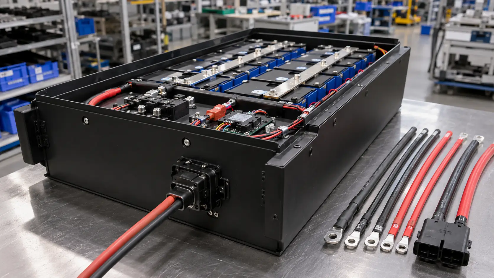
Chalongfly designs battery wiring harnesses together with custom LiFePO4 battery packs, so the output cables, high-current connectors, BMS, fuse, contactor and mechanical routing can be checked before the first sample is built.
24V, 48V and 72V packs do not use the same cable logic
Cable sizing should be reviewed according to equipment power and current profile. The points below show the typical engineering differences, not a universal battery cable size chart.
24V battery packs
24V systems are common in compact cleaning equipment, medical carts and smaller utility devices. Current can become high quickly when motors, pumps or actuators start.
- Higher current for the same power demand
- More sensitive to voltage drop
- Needs careful DC cable length control
- Connector heat should be checked early
48V battery packs
48V is widely used in industrial equipment because it balances current level, pack size and system integration. See our 48V LiFePO4 battery pack design guide.
- Lower current than 24V at similar power
- Still needs peak-current review
- Good platform for OEM equipment
- Charger and BMS limits must align
72V battery packs
72V systems are often used in higher-power motive applications such as AWP, industrial vehicles and larger mobile equipment where drive current and peak events matter.
- Lower current than 24V for the same power
- Insulation spacing and connector selection matter
- Peak current can still be demanding
- Service access and safety layout are important
| Design factor | Why it matters | What OEM should confirm | When to review |
|---|---|---|---|
| Continuous current | Continuous current determines long-term heat rise in cables, terminals and connectors. | Rated load, duty cycle, discharge duration and expected ambient temperature. | Before cable selection |
| Peak current | Motor start, lifting, acceleration or pump start can create short high-current events. | Peak current value, duration, frequency and whether the BMS allows it. | Before BMS setup |
| AWG / mm² cross-section | Wire gauge or cable cross-section affects current capacity, heat rise, bend radius and terminal compatibility. | Preferred AWG or mm² range, cable insulation, crimp terminal type and available routing space. | Before harness design |
| Cable length | Longer cables increase voltage drop and heat, especially in lower-voltage systems. | Battery-to-controller distance, internal cable route and equipment-side harness length. | Before layout freeze |
| Voltage drop | Excessive voltage drop can reduce equipment performance and trigger protection earlier. | Acceptable voltage drop under continuous and peak load conditions. | Before sample build |
| Connector rating | The connector may become the thermal bottleneck even if the cable is large enough. | Current rating, contact resistance, cable size range, mating cycles and vibration environment. | Before connector approval |
| Fuse and contactor | Protection components must match cable capacity, peak load and fault protection logic. | Fuse rating, contactor current, pre-charge needs and service disconnect method. | Before protection design |
| Routing and strain relief | Bending, vibration and unsupported cable exits can damage insulation or crimped joints. | Bend radius, clamps, cable glands, strain relief and service loops. | Before mechanical release |
A practical cable sizing process for OEM battery projects
Cable size should be selected together with the pack architecture, not after the battery sample is finished.
Do not size the cable from voltage and capacity alone
A 48V 200Ah pack and a 48V 300Ah pack may use different cables if their equipment loads are different. Likewise, a 24V pack with short cables may behave differently from a 24V pack with long equipment-side wiring. Current profile, AWG or mm² cable cross-section, connector rating and installation layout are more important than nominal capacity alone.
For higher-power industrial vehicles, also review pack voltage and drive system architecture. See our 96V lithium battery pack design guide.
Define load current
Confirm continuous current, peak current, peak duration and duty cycle from the equipment side.
Estimate voltage drop
Review total cable length, positive and negative return path, contact points and allowable performance loss.
Check thermal margin
Evaluate heat rise around cables, terminals, contactors, fuses and connectors inside the pack.
Match connector and protection
Coordinate cable size with connector rating, crimp terminal, fuse, contactor and BMS discharge limit.
Validate in equipment
Measure voltage drop, connector temperature and BMS behavior during real load, charging and peak events.
Cable sizing problems usually appear during real equipment operation
Many cable sizing issues are not visible during a simple battery capacity test. They appear when the equipment starts, accelerates, lifts, climbs, charges frequently or operates inside a compact battery compartment.
Using nominal current only
The equipment may have short peak loads that are much higher than the average current. Cable, connector and BMS settings must consider these events.
Oversizing cable but undersizing connector
A larger cable does not solve heat problems if the connector contact, terminal or crimp area becomes the bottleneck.
Ignoring cable routing inside the case
Tight bends, unsupported cable exits and routing near heat sources can reduce reliability even when the cable cross-section looks sufficient.
Not coordinating fuse and BMS limits
If the fuse, contactor and BMS current limits are not coordinated, the equipment may stop unexpectedly or fail to protect the cable path correctly.
Forgetting equipment-side cable length
The cable inside the battery pack is only one part of the circuit. The vehicle-side or equipment-side harness also affects voltage drop and heating.
Skipping temperature validation
Voltage drop and heat rise should be checked during real load and charging conditions, not only by visual inspection of the cable size.
What OEMs should provide for a cable sizing review
To size high-current battery cables correctly, the supplier needs the real electrical and mechanical environment, not only voltage and capacity.
FAQ about high-current cable sizing for LiFePO4 battery packs
Why do 24V battery packs usually need larger cables than 48V or 72V packs?
For the same equipment power, a lower-voltage battery system carries higher current. Higher current increases voltage drop and heat, so 24V systems often need larger cables or shorter cable runs than 48V or 72V systems under similar power demand.
Can cable size be selected only from the battery capacity?
No. Capacity does not define the cable size by itself. Cable sizing should consider continuous current, peak current, peak duration, cable length, voltage drop, temperature rise, connector rating, fuse coordination, BMS discharge limits and the real operating cycle of the equipment.
Should OEMs use an AWG or mm² battery cable size chart?
A battery cable size chart can be a starting reference, but it should not be the final design basis for an OEM LiFePO4 battery pack. The final AWG or mm² cable cross-section should be checked with continuous current, peak current, cable length, voltage drop, connector rating, installation temperature, routing space and BMS protection limits.
What happens if the battery cable is undersized?
An undersized cable can cause excessive voltage drop, cable heating, connector heating, unstable equipment performance, early BMS protection or long-term reliability issues. In severe cases, it can also stress terminals, crimps and protective components.
Should the connector be selected before or after cable sizing?
The connector should be selected together with the cable. The connector must support the required current, cable diameter, crimp terminal, mating direction, vibration environment, service access and temperature rise. Chalongfly is a TE Tier-1 distributor in China and can support TE connector selection and supply for OEM projects.
What information should an OEM send for cable sizing review?
The OEM should provide battery voltage, continuous current, peak current, peak duration, AWG or mm² cable preference, cable length, connector requirement, battery compartment drawing, charger current, BMS limit and equipment duty cycle. These inputs allow the supplier to review cable size, connector selection, routing and protection as one system.
Need help sizing high-current cables for a custom LiFePO4 battery pack?
Send the voltage platform, current profile, AWG or mm² cable requirement, cable length, connector requirement and battery compartment drawing. Chalongfly can review cable sizing, connector matching, BMS limits, fuse coordination and harness routing before sample production.