

BMS Communication Harness Connector & Pinout Design for Industrial Battery Packs
For industrial battery packs, the communication interface should be treated as a controlled engineering boundary. Connector family, cavity orientation, terminals, CAN or RS485 pair assignment, signal reference, shield path, keying and mating-half details should be frozen before pilot build.
There is no single universal connector pinout for all CAN- or RS485-based industrial battery packs.
CAN and RS485 define communication behavior. They do not, by themselves, define one battery connector housing or one cavity map for every industrial battery application.
Some CAN ecosystems do publish standardized or recommended connector pin assignments. For example, CiA 106 recommends connector pin assignments for CAN interfaces. An OEM battery pack should still follow the released project-specific interface drawing whenever the equipment, BMS, connector family or higher-layer specification defines its own interface.
Two industrial battery packs can both use CAN while assigning CAN-H, CAN-L, signal ground, wake, ignition, shield or service circuits to different cavities. The production reference should therefore be the released interface drawing—not memory, wire color or a similar-looking connector from another project.
Protocol definition
Defines electrical signaling, message transport and network behavior.
Physical interface definition
Defines housing, terminal, cavity orientation, signal, wire, seal, mating half and revision.
What belongs in a BMS communication interface drawing?
A useful interface drawing lets purchasing, harness engineering, production and equipment integration all reference the same controlled definition.
| Drawing field | Why it matters | Typical content | Common failure |
|---|---|---|---|
| Cavity number + view | Defines physical terminal position and prevents mirrored interpretation. | 1, 2, 3… plus mating-face or wire-entry view. | Correct signal, wrong physical cavity. |
| Signal name | Defines electrical function. | CAN-H, CAN-L, RS485-A/B, GND, WAKE, IGN. | Polarity assumed from wire color. |
| Wire specification | Controls conductor, insulation and pair construction. | Twisted pair, conductor size, temperature class. | Loose singles replace a controlled pair. |
| Terminal / seal | Controls crimp and environmental performance. | Terminal PN, seal, cavity plug, approved wire range. | Wrong terminal-to-wire combination. |
| Mating connector | Prevents field mismatch. | Equipment-side housing, terminal, keying and approved alternate. | Only battery-side half defined. |
| Revision control | Keeps BMS, harness and controller synchronized. | Drawing revision, ECN/ECR, release date and change owner. | Old harness built to obsolete pinout. |
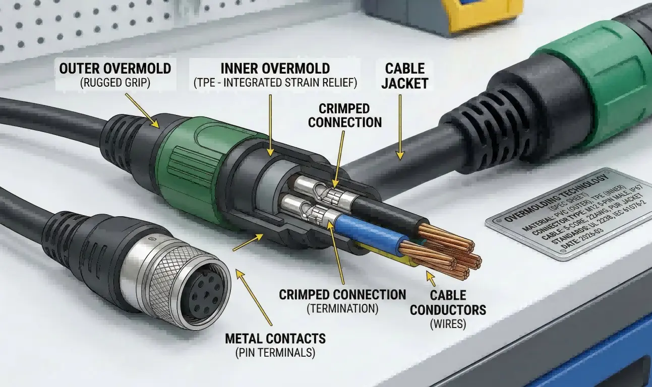
The connector system is more than a housing.
Terminal range, seal compatibility, overmold or strain relief, secondary lock and wire construction determine whether the interface remains stable through vibration, servicing and repeated mating cycles.
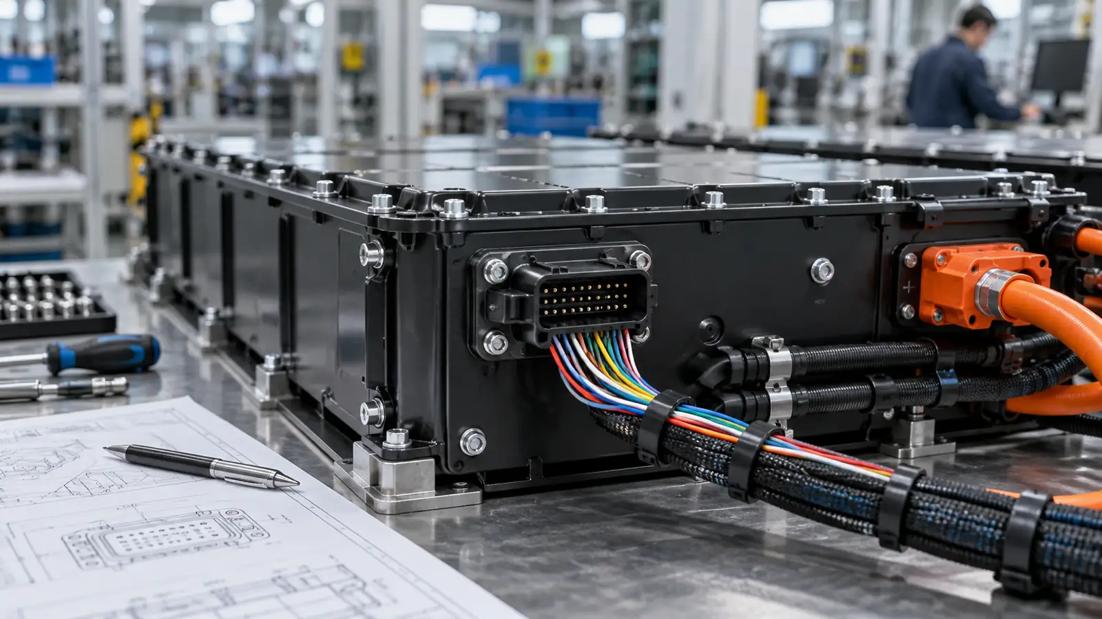
Reference image from CLF industrial cable assembly media libraryKeep differential communication pairs together through the connector transition.
CAN-H/CAN-L and RS485-A/RS485-B should remain controlled pairs through the harness and as close as practical to the terminal transition. Avoid unnecessary pair separation or long untwisted breakouts.
Whether a dedicated signal reference conductor is required depends on the isolation scheme, transceiver common-mode range and system grounding architecture. Define that conductor explicitly when required. Do not assume chassis, battery negative and signal ground are interchangeable. For shielded harnesses, define whether the shield terminates to a connector shell, drain wire, chassis bond or another approved EMC path.
Network termination is a separate topology decision. Do not assume a terminating resistor belongs inside the harness or connector unless the released CAN or RS485 network design explicitly requires it.
For EMC details, see How to Shield and Ground CAN/RS485 BMS Harnesses in Industrial Battery Packs.
Electrical fit is only one part of connector selection.
Electrical rating
Check the real terminal, wire size, temperature, cavity loading and system voltage.
Environment
Match sealing, temperature, vibration, fluids and ingress requirements.
Mechanical retention
Review latch, CPA, TPA, secondary lock and strain relief.
Serviceability
Allow technicians to identify and reconnect the interface without terminal damage.
When low-voltage communication and higher-energy circuits are present in the same interface area, separation, insulation coordination and connector ratings should be reviewed against the actual system safety architecture. Do not combine circuits merely to reduce connector count.
Keying, cavity orientation and secondary locks prevent field failures.
Where several similar connectors exist on the same battery or vehicle, mechanical coding and unambiguous drawing views reduce cross-mating, terminal push-back and mirrored pin interpretation.
A correct pin map can still fail if the terminal-to-wire combination is wrong.
The terminal must match conductor cross-section, insulation diameter, seal system and approved tooling. Interface review should therefore include both electrical mapping and production process compatibility.
Wire range
Verify conductor and insulation diameter against terminal and seal limits.
Crimp geometry
Control crimp height and width to the validated process specification.
Pull-force check
Use the correct acceptance requirement for conductor and terminal.
Terminal seating
Confirm primary lock, seal seating and TPA/secondary lock.
For the exact terminal and wire combination, crimp dimensions, tooling and acceptance limits should follow the connector manufacturer's application specification or other approved project specification. Generic workmanship standards should not replace the terminal supplier's validated application data.
Also review the OEM battery wiring harness design checklist and Chalongfly quality control process.

Freeze the interface before the pilot harness is built.
The best time to remove ambiguity is before tooling, harness fabrication and equipment integration begin.
What should an OEM send before connector and pinout review?
Validation before pilot build and mass production.
Verify every cavity against the released drawing.
Confirm no unintended contact between adjacent circuits.
Confirm polarity, reference conductor and required termination against the released network design.
Inspect latch, terminal push-back, seal and secondary lock.
Run the real BMS-controller interface under normal and relevant switching conditions.
Repeat continuity and communication after movement or vibration testing.
Continue the BMS harness engineering review.
Frequently asked connector and pinout questions.
Is there a standard CAN pinout for lithium battery packs?
There is no single universal battery-pack pinout used by every CAN application. Some ecosystems define or recommend connector pin assignments, such as CiA 106 for CAN interfaces. The released BMS and equipment interface drawing remains the production authority for the specific battery project.
Should signal ground always be included with CAN or RS485?
Not universally. The requirement depends on isolation, transceiver common-mode range and the system grounding architecture. Do not omit or add a reference conductor without checking both ends of the interface.
Can the cable shield use an ordinary signal pin?
Only if that termination method is intentionally designed and validated. Many systems instead use a drain wire, connector shell or chassis bond as part of the EMC architecture.
Why are A and B labels risky on RS485?
Because vendor documentation can use polarity terminology differently. Verify the actual transceiver truth table or equipment interface specification instead of relying only on the letters A and B.
What production test is essential for a pinout harness?
The released production test plan should include controlled pin-to-pin continuity and short-circuit isolation, typically on every harness unless the customer specification defines another method. Functional communication testing should then follow the project's required 100% or sampling plan.
Need a BMS connector and pinout reviewed before pilot build?
Send the BMS interface, mating connector, equipment pinout, communication requirements and mechanical constraints. Chalongfly can review the pin map, connector system, terminals, shielding path, keying, BOM change-control points and validation plan as part of an OEM battery pack project.