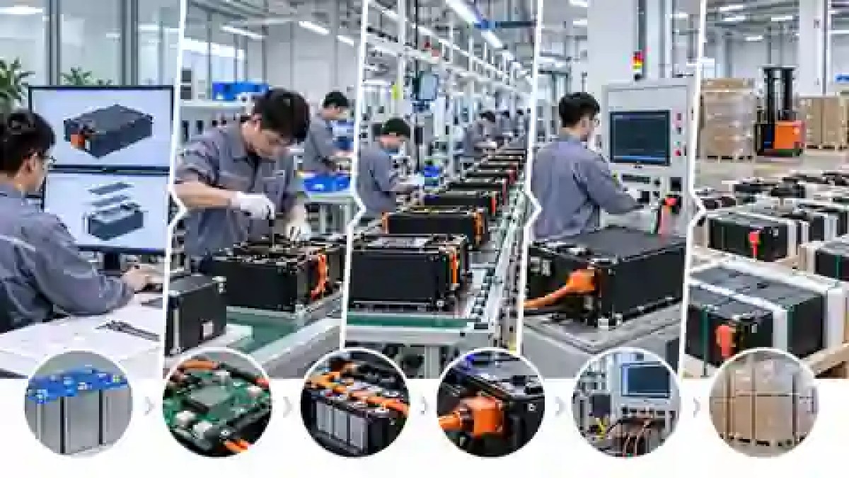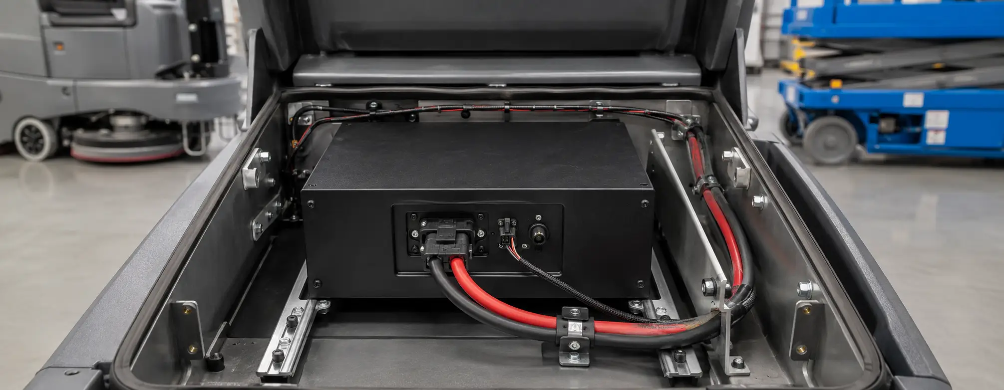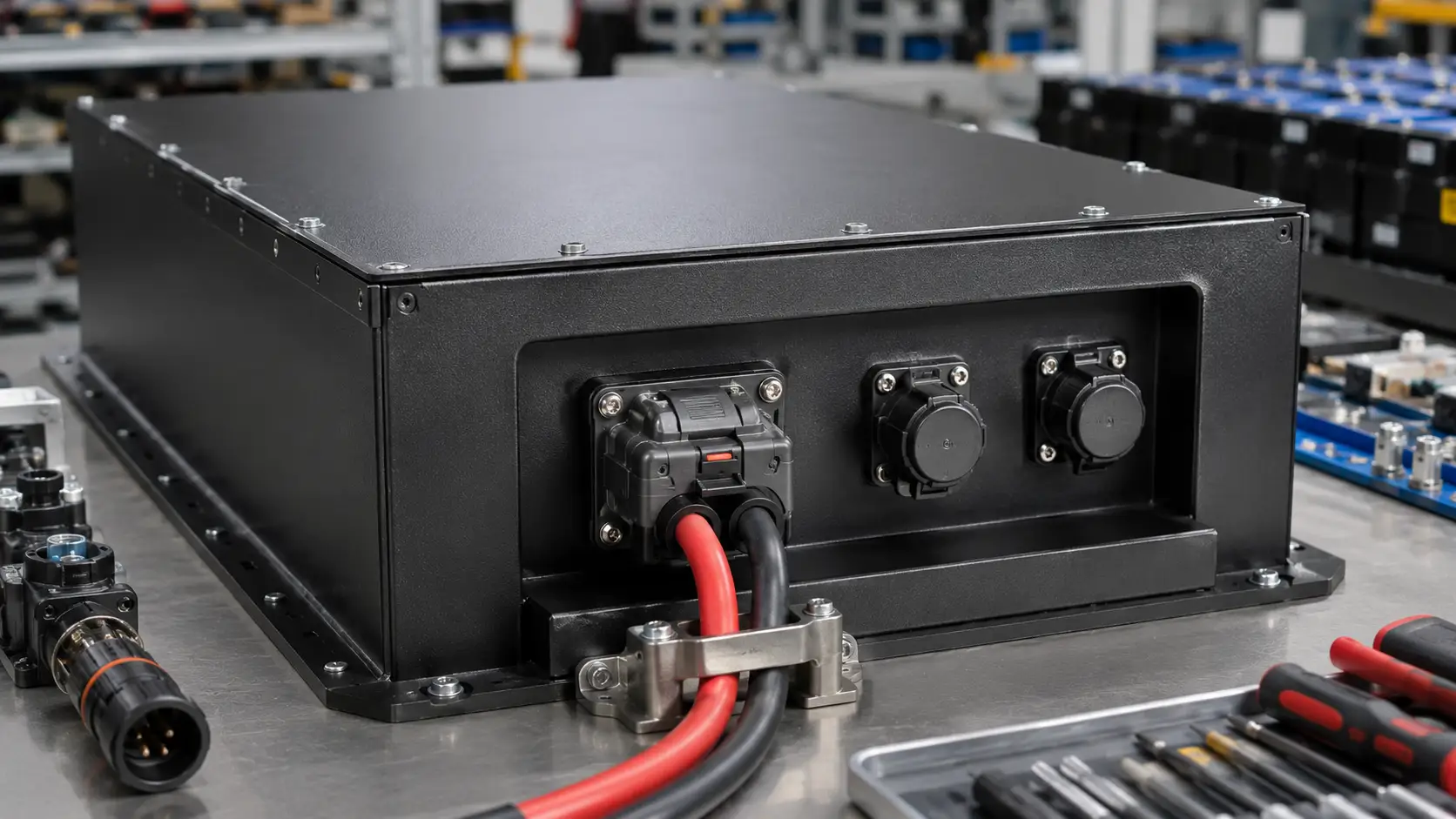


How to Shield and Ground CAN/RS485 BMS Harnesses in Industrial Battery Packs
Reliable CAN and RS485 communication depends on more than protocol choice. Twisted-pair construction, shield termination, grounding architecture, bus termination, connector bonding and routing near high-current switching paths can determine whether a battery communicates cleanly in real equipment or fails intermittently during validation.
Quick answer: should CAN or RS485 BMS wiring always be shielded?
No. A twisted differential pair is the starting point for both CAN and RS485, but shielding is not automatically required in every battery pack. Shielding becomes more valuable when the communication harness is long, runs near contactors, inverters, DC/DC converters, chargers or high-current conductors, or when EMC testing shows communication errors.
The shield strategy must be designed together with grounding and connector bonding. Adding a shield without a controlled termination path can create new problems instead of solving noise.
For the broader physical architecture, see our BMS signal harness design guide and our CANBus vs RS485 comparison.
1. Start with twisted pair
Keep each differential pair together through the complete route, including connector transitions where practical.
2. Separate noisy power paths
Avoid long parallel runs beside traction cables, contactor outputs and switching devices.
3. Define shield termination
Define the bond point and purpose on the drawing instead of leaving it as an assembly-time decision.
4. Validate under switching
Check communication while chargers, contactors and other real noise sources are operating.
Separate three concepts: signal reference, cable shield and chassis
Many BMS communication faults start because these three conductors are treated as interchangeable. They are not.
| Function | What it does | Common mistake | OEM review point |
|---|---|---|---|
| Signal reference / GND | Provides the electrical reference required by the communication interface when the transceiver design needs one. | Using chassis as the only reference without checking transceiver requirements. | Confirm the BMS and equipment-side interface schematic. |
| Cable shield / drain | Provides a controlled path for coupled noise away from the differential pair. | Connecting the shield randomly or through a long pigtail that weakens high-frequency performance. | Define shield bond point, connector shell strategy and drain-wire handling. |
| Chassis / enclosure bond | Provides the equipment reference for EMC and fault-current architecture where applicable. | Assuming battery negative and chassis are always the same electrical node. | Confirm vehicle or equipment grounding architecture before harness release. |
Termination and topology matter as much as shielding
A well-shielded cable can still communicate poorly if the physical bus is terminated incorrectly or if the topology creates excessive reflections.
| Design item | CAN | RS485 | OEM check |
|---|---|---|---|
| Pair construction | Use a controlled twisted differential pair for CAN-H / CAN-L. | Use a controlled twisted differential pair for A / B. | Record cable type and connector pin mapping. |
| Termination | Typical high-speed CAN buses use termination at the two physical ends of the main bus, commonly 120 Ω at each end. | RS485 commonly uses termination at the two physical ends when cable length and data rate require it, often near the cable characteristic impedance. | Measure actual end-to-end resistance with power off and compare with the network design. |
| Stubs | Keep branch stubs short relative to the data rate and bus length. | Avoid star wiring unless the transceiver or network design explicitly supports it. | Freeze topology before tooling the harness. |
| Bias / idle state | Usually managed by the CAN transceivers and termination architecture. | Some RS485 networks require failsafe biasing depending on the transceiver design. | Do not add external bias resistors without checking the BMS and controller circuitry. |
Reduce coupling before relying on the shield
Keep distance from switching nodes
Route away from contactors, inverter phase cables, charger switching sections and high-current busbars where layout allows.
Avoid long parallel runs
If signal and power paths must cross, a near-right-angle crossing is generally preferable to a long parallel route.
Protect pair geometry
Do not untwist large sections of CAN or RS485 pair near connectors. Keep the pair together to the termination area.
Use serviceable shield bonding
Shield clamps, connector shells and drain-wire terminations should remain inspectable after assembly.
How to verify a BMS communication harness before mass production
| Test | Purpose | What to record | Failure clue |
|---|---|---|---|
| Continuity + pin map | Confirm every communication and ground path reaches the intended connector pin. | Harness serial number, drawing revision, pass/fail. | Wrong pin order or intermittent crimp. |
| Termination resistance | Verify the assembled network matches the intended topology. | Measured resistance with system powered off. | Missing, duplicated or misplaced termination. |
| Oscilloscope check | Observe differential waveform quality at the BMS and equipment-side node. | CAN or RS485 differential levels, overshoot and ringing. | Reflection, weak common-mode margin or excessive noise. |
| Switching-noise test | Exercise the network while contactors, charger, DC/DC converter or traction controller operate. | Communication error count, resets, bus-off or timeout events. | Noise-sensitive routing or grounding. |
| Vibration / movement recheck | Confirm shielding and connector bonds stay stable after mechanical stress. | Post-test continuity and communication results. | Loose shell bond, drain-wire fatigue or connector movement. |
Connect this validation plan with the Chalongfly quality control process and the OEM battery wiring harness design checklist.
What should an OEM send for shielding and grounding review?
The supplier needs both the electrical interface and the physical equipment layout. Without both, shield and grounding decisions are guesswork.
Build the complete BMS harness topic cluster
FAQ: CAN and RS485 BMS harness shielding
Does a CAN bus cable need a shield?
Not always. A twisted pair is fundamental. Add shielding when the electromagnetic environment, cable length, routing or EMC test results justify it.
Should the cable shield connect to battery negative?
Not by default. Shield termination should follow the system grounding architecture. Battery negative, signal reference and chassis may be separate nodes.
Why can grounding the shield at both ends cause problems?
If two chassis points have a low-frequency voltage difference, shield current can circulate between them. At high frequency, however, multi-point or 360° bonding can improve EMC performance, so the strategy must be validated rather than assumed.
What resistance should I measure on a terminated CAN bus?
For a common high-speed CAN network with two 120 Ω terminators in parallel, a power-off measurement across CAN-H and CAN-L is typically about 60 Ω. The exact expected value depends on the actual topology.
Can CAN and RS485 run in the same battery harness?
Yes, if each differential pair is correctly defined, routed and terminated, and the connector and shielding strategy prevents unwanted coupling.
How should OEMs validate shielding before production?
Check continuity, pin mapping, termination resistance and communication waveforms, then repeat testing while real noise sources such as contactors, chargers and traction controllers are operating.
Need a CAN/RS485 BMS harness reviewed before pilot build?
Send the BMS interface, communication pinout, harness length, connector drawing and equipment grounding layout. Chalongfly can review routing, shield termination, grounding, connector selection and validation requirements as part of an OEM battery pack project.
Request a QuoteWhatsApp Us